


The following maximum deviations are laid down in DIN 2093. They are valid for all Schnorr disc springs as per the DIN and Schnorr works standards. In general Schnorr also apply these tolerances to special sizes, however, if they deviate greatly from the DIN springs, wider tolerances must be specified. This applies, for example, to our ball-bearing disc springs (section 8.1 and 9.5). If closer tolerances are required than those specified in DIN 2093, please contact us.
Diameter Tolerances
For the outside diameter De, the tolerance field h12 is applied, and for the inner diameter Di, it is H12.
For the concentricity the tolerances applied are:
for De to 50mm: 2 . IT 11
for Di over 50mm: 2 . IT 12
De or Di [mm] | Permissible deviation in mm | ||
De | Di | Concentricity | |
Over 3-6 | 0/-0.12 | +0.12/0 | 0.15 |
Over 6-10 | 0/-0.15 | +0.15/0 | 0.18 |
Over 10-18 | 0/-0.18 | +0.18/0 | 0.22 |
Over 18-30 | 0/-0.21 | +0.21/0 | 0.26 |
Over 30-50 | 0/-0.25 | +0.25/0 | 0.32 |
Over 50-80 | 0/-0.30 | +0.30/0 | 0.60 |
Over 80-120 | 0/-0.35 | +0.35/0 | 0.70 |
Over 120-180 | 0/-0.40 | +0.40/0 | 0.80 |
Over 180-250 | 0/-0.46 | +0.46/0 | 0.92 |
Over 250-315 | 0/-0.52 | +0.52/0 | 1.04 |
Over 315-400 | 0/-0.57 | +0.57/0 | 1.14 |
Over 400-500 | 0/-0.63 | +0.63/0 | 1.26 |
Thickness Tolerances
Tolerances allowed in DIN 2093 are as follows:
t or t’ [mm] | Tolerance at t [mm] | |
Group 1 | 0.2-0.6 | +0.02/-0/06 |
>0.6 -<1.25 | +0.03/-0.09 | |
Group 2 | 1.25-3.8 | +0.04/-0.12 |
>3.8-6.0 | +0.05/-0.15 | |
Group 3 | >6.0-16.0 | +0.30/-0.30 |
For springs in group 3 the tolerances is applied to the reduced thickness t’.
We used the thickness to ensure that spring loads are within tolerance and therefore will in some cases deviate from the above figures.
Overall Height Tolerances
To ensure the specified spring forces, DIN 2093 allows the overall height tolerance to be slightly exceeded.
t [mm] | Tolerance at lo [mm] | |
Group 1 | <1.25 | +0.10/-0.05 |
Group 2 | 1.25-2.0 | +0.15/-0.08 |
>2.0-3.0 | +0.20/-0.10 | |
>3.0-6.0 | +0.30/-0.15 | |
Group 3 | >6.0-16.0 | +0.30/-0.30 |
Load Tolerances
Single Disc Springs
For single disc springs the following maximum deviations are allowed:
t [mm] | Tolerance for F at the test length lp=lo-0.75 ho | |
Group 1 | <1.25 | +25%/-7.5% |
Group 2 | 1.25-3.0 | +15%/-7.5% |
>3.0-6.0 | +10%/-5% | |
Group 3 | >6.0-6.0 | +5%/-5% |
With a single spring the spring force must be checked at the height lo – s. This should be carried out with the spring pressed between two lubricated, hardened, ground and polished plates. Measurements are always taken in loading direction.
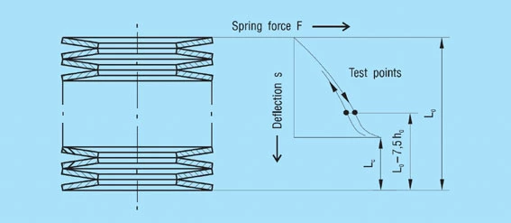
For the determination of the variation between loading and unloading, a stack of 10 springs in single series is used. The stack is fitted with a guide rod and abutment plates inserted at both ends. Before testing, the stack should be loaded with twice the spring force F(s = 0.75 ho).
During unloading the measured spring force at the length Lo – 7.5 ho must at least reach the percentage of the loading characteristic shown in the table (figure 28).
Figure 28 – click to enlarge