


Schnorr Disc Springs
CHARACTERISTICS OF A SINGLE SPRING
Disc Spring Engineering
Maximum load - minimum space - maximum flexibility
CHARACTERISTICS OF A SINGLE SPRING
The value ho/t determines the amount of curvature of the spring characteristics (figure 3). For ho/t < 0.4, thecharacteristics is almost linear, as the value ho/t increases, the curve becomes more regressive. At ho/t = √2 the curve has a nearly horizontal segment (at s = ho it has a horizontal tangent). This means that springs can be developed with an almost horizontal characteristic, which gives very little load increase with deflection. However, this type of spring with ho/t > 1.3 is not suitable for long spring stacks, as individual springs within the stack may move unevenly and be overloaded. As a result, such springs should only be used alone.
Figure 3 – click to enlarge
Figure 8 – Click to enlarge
On the other hand, the force of the flattened disc spring increases linearly. If, for example, a spring calculation cannot predict this in a satisfactory manner, then a first step in the form of a change in the free height may already produce the desired load/deflection diagram. Here, however, the permissible stress must be observed, as these increase with increasing cone height ho.
At ho/t > √2, the spring force reaches a maximum and then decreases again. In some cases the decreasing segment of the curve is utilised. Under certain conditions the spring must be loaded beyond the flat position, for which certain design conditions must be given (figure 9).
Figure 9 – Click to enlarge
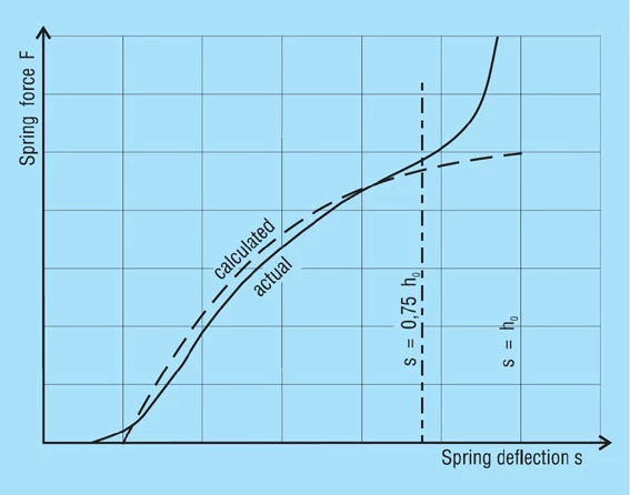
For the normal arrangement of disc springs a progressive increase in the spring force occurs at deflections of s > 0.75 ho which deviates from the calculated value. This results from the shift in the load points to smaller lever arms, because the disc springs roll on each other or on the abutments. Therefore, it is recommended that only approx. 75 to 80% of the spring deflection is utilised. For this reason, the spring force is only indicated at s ≈ 0.75 ho in DIN 2093 (figure 10).
Figure 10 – Click to enlarge