


Schnorr Disc Springs
Schnorr Disc Springs Calculation Examples
Disc Spring Engineering
Maximum load - minimum space - maximum flexibility
Basic Calculation Examples
The ‘life lines’ also allow the fatigue life to be estimated for various working strokes. In spite of this we show several examples of the calculation and checking of disc springs below.
Example 1: Checking fatigue life of a disc spring
Given:
Spring 45 x 22.4 x 1.75; lo = 3.05mm (figure 11)
Preload F1 = 1580N
Final Load F2 = 2670N
Frequency f = 1000/min
To be determined:
Is the stress within the acceptable range – what is the estimated fatigue life.
Solution:
From the tables of disc springs we can obtain the following data:
s/ho s[mm] F[N] s[N/mm2]
0.25 0.325 1524 433
0.5 0.650 2701 814
0.75 0.980 3659 1148
1.0 1.300 4475 1421
With the help of these four points the load and stress relative to the deflection may be drawn.
Figure 11 – click to enlarge
Disc spring 45 x 22.4 x 1.75; lo = 3.05 mm
The following values may be obtained from the diagram (figure 12):
S1 = 0.34mm, S2 = 0.64mm
σu = 450 N/mm2
σo= 804 N/mm2
From the fatigue diagram for group 2 springs figure 19, we obtain σu 450 N/mm2 with a maximum stress of σ0= 920 N/mm2. Therefore the spring is fatigue resistant as σo < σ0.
Figure 12 – click to enlarge
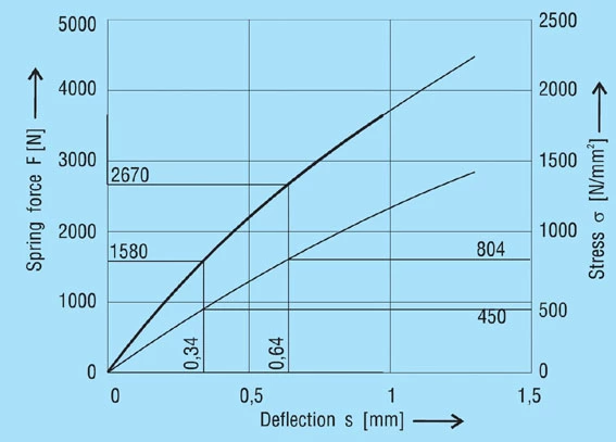
Diagram for spring 45 x 22.4 x 1.75 mm, lo = 3.05 mm
Example 2: Disc spring with a high ho/t ration
Given:
Guide diameter 30mm
Installed length l1 = 4,9mm
Preload F1 = 2000 N min.
Working defl. s2 – s1 = 1.05mm
Spring load F2 = 2500 N max.
Required:
Suitable disc spring dimensions
Solution:
Spring inside diameter Di = 30.5mm
Spring outside diameter De = 60mm (selected because of the favourable De/Di ratio)
Because of the very small load range and the small installed length only a spring with a high ho/t ratio is suitable.
Selected:
Disc spring 60 x 30.5 x 1.5mm (figure 13); lo = 3.5mm ho/t = 1.333; δ = 1.967
Calculation:
First the factors are calculated using formula 3, 4 and 5:
K1 = 0.688
K2 = 1.212
K3 = 1.365
Figure 13 – click to enlarge
Disc spring 60 x 30.5 x 1.5 mm
The stress σOM can be checked using formula 9: σOM = -1048 N/mm2.
This value lies well under the limit of -1600 N/mm2, the spring will therefore not set. Now the spring loads can be calculated to formula 8a, preferably for the 4 deflections s = 0.25 ho, s = 0.5 ho, s = 0.75 ho and s = ho.
One obtains the following values:
s/ho s[mm] F[N]
0.25 0.5 1338
0.5 1.0 2058
0.75 1.5 2367
1.0 2.0 2469
With these 4 points the spring diagram can be drawn.
Figure 14 – Click to enlarge
Diagram for spring 60 x 30.5 x 1.5 mm, lo = 3.5 mm
One can read F1 = 2100 N s1 = 1.05mm
and for F2 = 2400 N s2 = 1.61mm
Deflection s2 – s1= 0.56mm
The deflection of a single spring is not sufficient, therefore two in series must be used.
This arrangement gives:
Unloaded length Lo=7.0mm
Preloaded length L1=4.90mm
Preloaded deflection s1=2.1mm
Preload F1=2100N
Deflection s2=s1+1.05=3.15mm
Final load F2=2390N
To check the fatigue life we must use the stresses at s1 = 1.05 and s2 = 1.575mm. Figure 17 shows that point lll is the dominant one, this gives:
s1: σu = 843 N/mm2
s2: σu = 1147 N/mm2
By utilising the fatigue life diagram in figure 19 we can see that the expected life will be in the order of 1,000,000 cycles.
Example 3: Calculation of a disc spring with contact flats
Given:
Disc spring 200 x 82 x 12mm; lo = 16.6mm
Ho = 4.6mm; δ = 2.439; ho/t = 0.383
Required:
The spring characteristics and the stresses σll and σlll.
Although this spring is to our works standard we show below how the calculations are made and results can be checked in the disc springs dimension tables.
From the formula 3 to 5 we first calculate the constants K1 to K3:
K1 = 0.755
K2 = 1.315
K3 = 1.541
The static design can be checked by the calculation of σOM, the reduced thickness is not considered and we use the values of t and ho. This gives:
σOM = -1579 N/mm2
As the acceptable value for σOM is 1600 N/mm2, the spring is correct. From figure 6 and considering d and ho/t the reduction factor t’/t can be obtained:
t’/t = 0.958
Therefore t’ = 11.5mm and ho’ = 5.1mm. Constant K4 can be calculated from formula 6: K4 = 1.0537.
Figure 15 – Click to enlarge
Disc spring 200 x 82 x 12 mm
Figure 16 – click to enlarge
Spring force and stresses for spring 200 x 82 x 12 mm, t’ = 11.5 l0 = 6.6 mm
Now from formula 8b, 11 and 12 the spring force and both stresses can be calculated.
s/ho s[mm] F[N]
σll
[N/mm2]
σlll
[N/mm2]
0.25 1.15 66924 416 389
0.5 2.3 127191 890 747
0.75 3.45 182838 1421 1072
1.0 4.6 235503 2011 1366
With this spring the greater values of stress are on the inner diameter which should be used. Finally the value of the stress σOM for the reduced thickness can be checked:
σOM’ = σOM . K4 . t’/t
σOM’ = -1595 N/mm2


